ASTM F1941 Specification
- Coating accommodation tolerances for externally coarse threaded (unc) fasteners
- Coating Accommodation Tolerances for Externally Fine Threaded (UNF) Fasteners
- Coating Accommodation Tolerances for Externally Threaded (UNS) Fasteners
- Coating Accommodation Tolerances for Externally Threaded (UN) Fasteners
Coating accommodation tolerances for externally and internally threaded fasteners
-
This specification does not impose maximum thickness values on high current density areas, where the coating thickness tends to be the greatest. On an externally threaded fastener this occurs at the threaded tip. Measuring coating thickness on the threaded portion of a fastener is possible but impractical for in-process quality control verification. For this reason the control mechanism specified in this document is by means of GO thread gauges. Nevertheless Tables X3.1-X3.4 illustrate maximum coating thickness permitted by Class 1A and 2A allowance, and are supplied as an informative guideline.
Note — The following information is based on ASME B1.1 Section 7. That standard should be consulted for more detailed information.
Size limits for standard external 1A and 2A thread classes apply prior to coating. The external thread allowance may thus be used to accommodate the coating thickness on threaded fasteners, provided the maximum coating thickness is no more than 1⁄4 of the allowance. Thus, threads after coating are subject to acceptance using a basic Class 3A GO gage and a class 2A gage as a NOT-GO gage.
In certain cases size limits must be adjusted, within the tolerances, prior to coating, in order to insure proper thread fit. This applies to the following cases:
Standard internal threads, because they provide no allowance for coating thickness.
Where the external thread has no allowance, such as Class 3A threads. - Coating accommodation tolerances for externally coarse threaded (unc) fasteners
- Coating Accommodation Tolerances for Externally Fine Threaded (UNF) Fasteners
- Coating Accommodation Tolerances for Externally Threaded (UNS) Fasteners
- Coating Accommodation Tolerances for Externally Threaded (UN) Fasteners
| Thread Pitch, TP |
Diameter, in | Pitch Diameter Allowance for 1A and 2A Thread Classes, in. |
Maximum Allowable Coating Thickness on Threaded Tip x 0.0001 in. |
|---|---|---|---|
| 20 | 1⁄4 | 0.0011 | 2.75 |
| 18 | 5⁄16 | 0.0012 | 3.00 |
| 16 | 3⁄8 | 0.0013 | 3.25 |
| 14 | 7⁄16 | 0.0014 | 3.50 |
| 13 | 1⁄2 | 0.0015 | 3.75 |
| 12 | 9⁄16 | 0.0016 | 4.00 |
| 11 | 5⁄8 | 0.0016 | 4.00 |
| 10 | 3⁄4 | 0.0018 | 4.50 |
| 9 | 7⁄8 | 0.0019 | 4.75 |
| 8 | 1 | 0.0020 | 5.00 |
| 7 | 1 1⁄8 and 1 1⁄4 | 0.0022 | 5.50 |
| 6 | 1 3⁄8 and 1 1⁄2 | 0.0024 | 6.00 |
| 5 | 1 1⁄4 | 0.0027 | 6.75 |
| 4 1⁄2 | 2 and 2 1⁄4 | 0.0029 | 7.25 |
| 4 | 2 1⁄2 | 0.0031 | 7.75 |
| 4 | 2 3⁄4 and 3 | 0.0032 | 8.00 |
| 4 | 3 1⁄4 and 3 1⁄2 | 0.0033 | 8.25 |
| 4 | 3 3⁄4 and 4 | 0.0034 | 8.50 |
Where allowance must be maintained after coating
for trouble free thread fit.
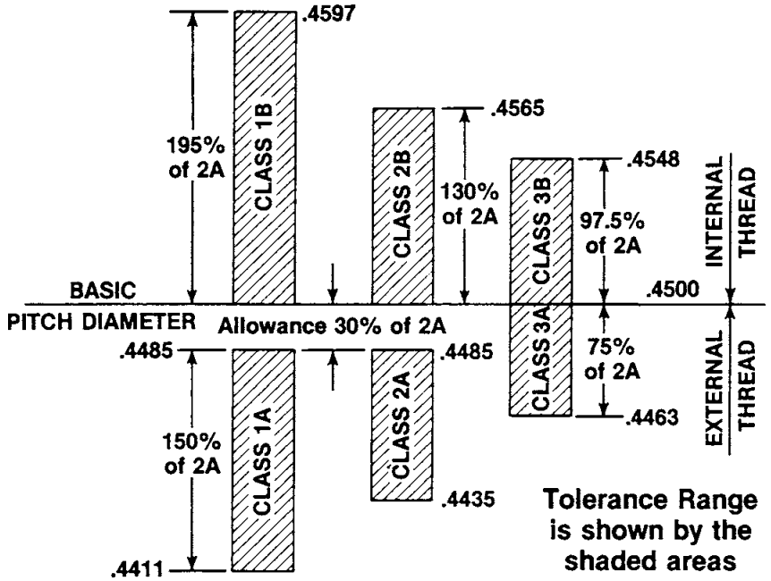
Tables X3.1-X3.4 provide maximum thickness values
based only on the allowance for the 1A and 2A thread classes.
It assumes that the external thread pitch diameter is at the
maximum and that the internal thread pitch diameter is at the
minimum of the tolerance (see Fig. X3.1).
| Thread Pitch, TPI |
Diameter, in | Pitch Diameter Allowance for 1A and 2A Thread Classes, in. | Maximum Allowable Coating Thickness on Threaded Tip, 3 0.0001 in. |
|---|---|---|---|
| 28 | 1⁄4 | 0.0010 | 2.50 |
| 24 | 5⁄16 and 3⁄8 | 0.0011 | 2.75 |
| 20 | 7⁄16 and 1⁄2 | 0.0013 | 3.25 |
| 18 | 9⁄16 and 5⁄8 | 0.0014 | 3.50 |
| 16 | 3⁄4 | 0.0015 | 3.75 |
| 14 | 7⁄8 | 0.0016 | 4.00 |
| 12 | 1, 1 1⁄8 and 1 1⁄4 | 0.0018 | 4.50 |
| 12 | 1 3⁄8 and 1 1⁄2 | 0.0019 | 4.75 |
| Thread Pitch, TPI |
Diameter, in | Pitch Diameter Allowance for 1A and 2A Thread Classes, in. | Maximum Allowable Coating Thickness on Threaded Tip, x 0.0001 in. |
|---|---|---|---|
| 14 | 1 | 0.0017 | 4.25 |
| Thread Pitch, TPI |
Diameter, in | Pitch Diameter Allowance for 1A and 2A Thread Classes, in. | Maximum Allowable Coating Thickness on Threaded Tip, x 0.0001 in. |
|---|---|---|---|
| 8 | 1 1⁄8 and 1 1⁄4 | 0.0021 | 5.25 |
| 8 | 1 3⁄8 , 1 1⁄2 and 1 5⁄8 | 0.0022 | 5.50 |
| 8 | 1 3⁄4 , 1 7⁄8 and 2 | 0.0023 | 5.75 |
| 8 | 2 1⁄4 and 2 1⁄2 | 0.0024 | 6.00 |
| 8 | 2 3⁄4 | 0.0025 | 6.25 |
| 8 | 3, 3 1⁄4 and 3 1⁄2 | 0.0026 | 6.50 |
| 8 | 3 3⁄4 and 4 | 0.0027 | 6.75 |

Relationship of Pitch Diameter Allowance for Classes of Fit on 1⁄2-13 UNC Thread