ASME B18.2.6M
- Dimensions of Metric Heavy Hex Structural Bolts.
- Maximum Grip Gaging Lengths and Minimum Body Lengths for Metric Heavy Hex Structural Bolts.
- Dimensions of Metric Heavy Hex Nuts for Use With Structural Bolts.
- Dimensions of Metric Hardened Steel Circular and Circular Clipped Washers.
- Dimensions for Metric Compressible Washer-Type Direct Tension Indicators.
ASME B18.2.6M
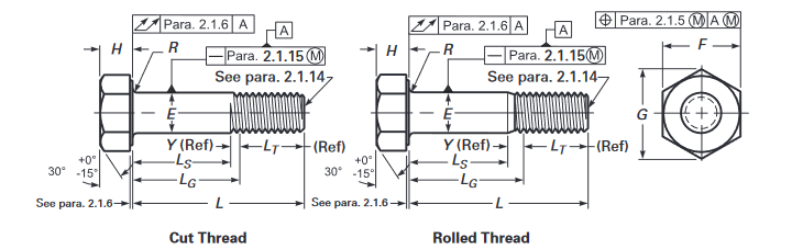
ASME B18.2.6M :- Dimensions of Metric Heavy Hex Structural Bolts
| Body Diameter, E |
AF, F | AC, G | Head Height, H |
Minimum Fillet Radius, |
Thread Length, |
Maximum Transition Thread Length, |
Maximum Runout of Bearing |
|||||
|---|---|---|---|---|---|---|---|---|---|---|---|---|
| Pitch | Max. | Min. | Max. | Min. | Max. | Min. | Max. | Min. | R | LT, Ref. | Y, Ref. | Surface FIM |
| M12 × 1.75 | 12.70 | 11.30 | 21.00 | 20.16 | 24.25 | 22.78 | 7.95 | 7.05 | 0.60 | 25 | 5.2 | 0.4 |
| M16 × 2 | 16.70 | 15.30 | 27.00 | 26.16 | 31.18 | 29.56 | 10.75 | 9.25 | 0.60 | 31 | 6.0 | 0.5 |
| M20 × 2.5 | 20.84 | 19.16 | 34.00 | 33.00 | 39.26 | 37.29 | 13.40 | 11.60 | 0.80 | 36 | 7.5 | 0.6 |
| M22 × 2.5 | 22.84 | 21.16 | 36.00 | 35.00 | 41.57 | 39.55 | 14.90 | 13.10 | 0.80 | 38 | 7.5 | 0.6 |
| M24 × 3 | 24.84 | 23.16 | 41.00 | 40.00 | 47.34 | 45.20 | 15.90 | 14.10 | 1.00 | 41 | 9.0 | 0.7 |
| M27 × 3 | 27.84 | 26.16 | 46.00 | 45.00 | 53.12 | 50.85 | 17.90 | 16.10 | 1.20 | 44 | 9.0 | 0.8 |
| M30 × 3.5 | 30.84 | 29.16 | 50.00 | 49.00 | 57.74 | 55.37 | 19.75 | 17.65 | 1.20 | 49 | 10.5 | 0.9 |
| M36 × 4 | 37.00 | 35.00 | 60.00 | 58.80 | 69.28 | 66.44 | 23.55 | 21.45 | 1.50 | 56 | 12.0 | 1.0 |
GENERAL NOTE: See Table 2 for LG and LS dimensions.
ASME B18.2.6M :- Maximum Grip Gaging Lengths and Minimum Body Lengths for Metric Heavy Hex Structural Bolts
| Nominal Bolt Diameter and Thread Pitch | |||||||||||||||||
|---|---|---|---|---|---|---|---|---|---|---|---|---|---|---|---|---|---|
| Nominal Length, |
M12 × 1.75 | M16 × 2 | M20 × 2.5 | M22 × 2.5 | M24 × 3 | M27 × 3 | M30 × 3.5 | M36 × 4 | |||||||||
| L G, | L S, | L G, | L S, | L G, | L S, | L G, | L S, | L G, | L S, | L G, | L S, | L G, | L S, | L G, | L S, | ||
| Max. | Min. | Max. | Min. | Max. | Min. | Max. | Min. | Max. | Min. | Max. | Min. | Max. | Min. | Max. | Min. | ||
| 40 | 15 | 9.8 | ... | ... | ... | ... | ... | ... | ... | ... | ... | ... | ... | ... | ... | ... | |
| 45 | 20 | 14.8 | 14 | 8 | ... | ... | ... | ... | ... | ... | ... | ... | ... | ... | ... | ... | |
| 50 | 25 | 19.8 | 19 | 13 | 14 | 6.5 | ... | ... | ... | ... | ... | ... | ... | ... | ... | ... | |
| 55 | 30 | 24.8 | 24 | 18 | 19 | 11.5 | 17 | 9.5 | ... | ... | ... | ... | ... | ... | ... | ... | |
| 60 | 35 | 29.8 | 29 | 23 | 24 | 16.5 | 22 | 14.5 | 19 | 10 | ... | ... | ... | ... | ... | ... | |
| 65 | 40 | 34.8 | 34 | 28 | 29 | 21.5 | 27 | 19.5 | 24 | 15 | 21 | 12 | ... | ... | ... | ... | |
| 70 | 45 | 39.8 | 39 | 33 | 34 | 26.5 | 32 | 24.5 | 29 | 20 | 26 | 17 | 21 | 10.5 | ... | ... | |
| 75 | 50 | 44.8 | 44 | 38 | 39 | 31.5 | 37 | 29.5 | 34 | 25 | 31 | 22 | 26 | 15.5 | ... | ... | |
| 80 | 55 | 49.8 | 49 | 43 | 44 | 36.5 | 42 | 34.5 | 39 | 30 | 36 | 27 | 31 | 20.5 | 19 | 7 | |
| 85 | 60 | 54.8 | 54 | 48 | 49 | 41.5 | 47 | 39.5 | 44 | 35 | 41 | 32 | 36 | 25.5 | 24 | 12 | |
| 90 | 65 | 59.8 | 59 | 53 | 54 | 46.5 | 52 | 44.5 | 49 | 40 | 46 | 37 | 41 | 30.5 | 29 | 17 | |
| 95 | 70 | 64.8 | 64 | 58 | 59 | 51.5 | 57 | 49.5 | 54 | 45 | 51 | 42 | 46 | 35.5 | 34 | 22 | |
| 100 | 75 | 69.8 | 69 | 63 | 64 | 56.5 | 62 | 54.5 | 59 | 50 | 56 | 47 | 51 | 40.5 | 39 | 27 | |
| 110 | ... | ... | 79 | 73 | 74 | 66.5 | 72 | 64.5 | 69 | 60 | 66 | 57 | 61 | 50.5 | 44 | 32 | |
| 120 | ... | ... | 89 | 83 | 84 | 76.5 | 82 | 74.5 | 79 | 70 | 76 | 67 | 71 | 60.5 | 54 | 42 | |
| 130 | ... | ... | 99 | 93 | 94 | 86.5 | 92 | 84.5 | 89 | 80 | 86 | 77 | 81 | 70.5 | 64 | 52 | |
| 140 | ... | ... | 109 | 103 | 104 | 96.5 | 102 | 94.5 | 99 | 90 | 96 | 87 | 91 | 80.5 | 74 | 62 | |
| 150 | ... | ... | 119 | 113 | 114 | 106.5 | 112 | 104.5 | 109 | 100 | 106 | 97 | 101 | 90.5 | 84 | 72 | |
| 160 | ... | ... | 129 | 123 | 124 | 116.5 | 122 | 114.5 | 119 | 110 | 116 | 107 | 111 | 100.5 | 94 | 82 | |
| 170 | ... | ... | 139 | 133 | 134 | 126.5 | 132 | 124.5 | 129 | 120 | 126 | 117 | 121 | 110.5 | 104 | 92 | |
| 180 | ... | ... | 149 | 143 | 144 | 136.5 | 142 | 134.5 | 139 | 130 | 136 | 127 | 131 | 120.5 | 114 | 102 | |
| 190 | ... | ... | 159 | 153 | 154 | 146.5 | 152 | 144.5 | 149 | 140 | 146 | 137 | 141 | 130.5 | 124 | 112 | |
| 200 | ... | ... | 169 | 163 | 164 | 156.5 | 162 | 154.5 | 159 | 150 | 156 | 147 | 151 | 140.5 | 134 | 122 | |
| 210 | ... | ... | 179 | 173 | 174 | 166.5 | 172 | 164.5 | 169 | 160 | 166 | 157 | 161 | 150.5 | 144 | 132 | |
| 220 | ... | ... | 189 | 183 | 184 | 176.5 | 182 | 174.5 | 179 | 170 | 176 | 167 | 171 | 160.5 | 154 | 142 | |
| 230 | ... | ... | 199 | 193 | 194 | 186.5 | 192 | 184.5 | 189 | 180 | 186 | 177 | 181 | 170.5 | 164 | 152 | |
| 240 | ... | ... | 209 | 203 | 204 | 196.5 | 202 | 194.5 | 199 | 190 | 196 | 187 | 191 | 180.5 | 174 | 162 | |
| 250 | ... | ... | 219 | 213 | 214 | 206.5 | 212 | 204.5 | 209 | 200 | 206 | 197 | 201 | 190.5 | 184 | 172 | |
| 260 | ... | ... | 229 | 223 | 224 | 216.5 | 222 | 214.5 | 219 | 210 | 216 | 207 | 211 | 200.5 | 194 | 182 | |
| 270 | ... | ... | 239 | 233 | 234 | 226.5 | 232 | 224.5 | 229 | 220 | 226 | 217 | 221 | 210.5 | 204 | 192 | |
| 280 | ... | ... | 249 | 243 | 244 | 236.5 | 242 | 234.5 | 239 | 230 | 236 | 227 | 231 | 220.5 | 214 | 202 | |
| 290 | ... | ... | 259 | 253 | 254 | 246.5 | 252 | 244.5 | 249 | 240 | 246 | 237 | 241 | 230.5 | 224 | 212 | |
| 300 | ... | ... | 269 | 263 | 264 | 256.5 | 262 | 254.5 | 259 | 250 | 256 | 247 | 251 | 240.5 | 234 | 222 | |
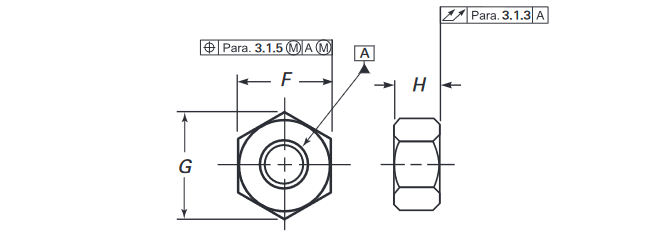
ASME B18.2.6M :- Dimensions of Metric Heavy Hex Nuts for Use With Structural Bolts
| Pitch | Width Across Flats, F | Width Across Corners, G | Thickness, H | Maximum Total Runout of Bearing |
|||
|---|---|---|---|---|---|---|---|
| Max. | Min. | Max. | Min. | Max. | Min. | Surface FIM | |
| M12 × 1.75 | 21.00 | 20.16 | 24.25 | 22.78 | 12.3 | 11.9 | 0.38 |
| M16 × 2.00 | 27.00 | 26.16 | 31.18 | 29.56 | 17.1 | 16.4 | 0.47 |
| M20 × 2.50 | 34.00 | 33.00 | 39.26 | 37.29 | 20.7 | 19.4 | 0.58 |
| M22 × 2.50 | 36.00 | 35.00 | 41.57 | 39.55 | 23.6 | 22.3 | 0.63 |
| M24 × 3.00 | 41.00 | 40.00 | 47.34 | 45.20 | 24.2 | 22.9 | 0.72 |
| M27 × 3.00 | 46.00 | 45.00 | 53.12 | 50.85 | 27.6 | 26.3 | 0.80 |
| M30 × 3.50 | 50.00 | 49.00 | 57.74 | 55.37 | 30.7 | 29.1 | 0.87 |
| M36 × 4.00 | 60.00 | 58.80 | 69.28 | 66.44 | 36.6 | 35.0 | 1.05 |
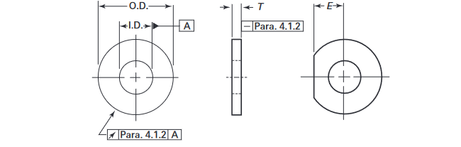
ASME B18.2.6M :- Dimensions of Metric Hardened Steel Circular and Circular Clipped Washers
| T | |||||||||
|---|---|---|---|---|---|---|---|---|---|
| Nominal Size | I.D. | O.D. | Standard | Extra Thick | Clipped Width, E, Min. | ||||
| [Note (1)] | Max. | Min. | Max. | Min. | Max. | Min. | Max. | Min. | [Note (2)] |
| 12 | 14.4 | 14.0 | 27.0 | 25.7 | 4.6 | 3.1 | 10.0 | 8.0 | 10.5 |
| 16 | 18.4 | 18.0 | 34.0 | 32.4 | 4.6 | 3.1 | 10.0 | 8.0 | 14.0 |
| 20 | 22.5 | 22.0 | 42.0 | 40.4 | 4.6 | 3.1 | 10.0 | 8.0 | 17.5 |
| 22 | 24.5 | 24.0 | 44.0 | 42.4 | 4.6 | 3.4 | 10.0 | 8.0 | 19.2 |
| 24 | 26.5 | 26.0 | 50.0 | 48.4 | 4.6 | 3.4 | 10.0 | 8.0 | 21.0 |
| 27 | 30.5 | 30.0 | 56.0 | 54.1 | 4.6 | 3.4 | 10.0 | 8.0 | 23.6 |
| 30 | 33.6 | 33.0 | 60.0 | 58.1 | 4.6 | 3.4 | 10.0 | 8.0 | 26.2 |
| 36 | 39.6 | 39.0 | 72.0 | 70.1 | 4.6 | 3.4 | 10.0 | 8.0 | 31.5 |
| 42 | 45.6 | 45.0 | 84.0 | 81.8 | 7.2 | 4.6 | 10.0 | 8.0 | 36.7 |
| 48 | 52.7 | 52.0 | 95.0 | 92.8 | 7.2 | 4.6 | 10.0 | 8.0 | 42.0 |
| 56 | 62.7 | 62.0 | 107.0 | 104.8 | 8.7 | 6.1 | 10.0 | 8.0 | 49.0 |
| 64 | 70.7 | 70.0 | 118.0 | 115.8 | 8.7 | 6.1 | 10.0 | 8.0 | 56.0 |
| 72 | 78.7 | 78.0 | 130.0 | 127.5 | 8.7 | 6.1 | 10.0 | 8.0 | 63.0 |
| 80 | 86.9 | 86.0 | 142.0 | 139.5 | 8.7 | 6.1 | 10.0 | 8.0 | 70.0 |
| 90 | 96.9 | 96.0 | 159.0 | 156.5 | 8.7 | 6.1 | 10.0 | 8.0 | 78.7 |
| 100 | 107.9 | 107.0 | 176.0 | 173.5 | 8.7 | 6.1 | 10.0 | 8.0 | 87.5 |
GENERAL NOTE:
(1) Nominal washer sizes are intended for use with comparable nominal
bolt diameters.
(2) Clipped edge, E, shall not be closer than 0.875 times the nominal bolt diameter
from the center of the washer.
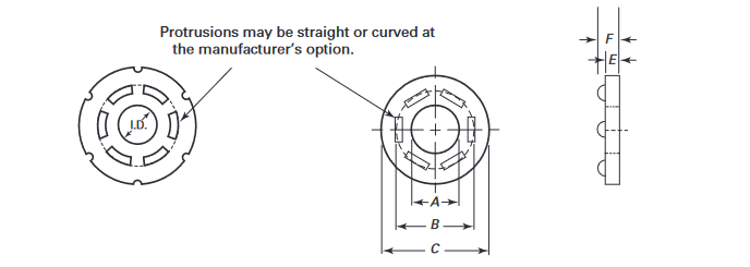
ASME B18.2.6M :- Dimensions for Metric Compressible Washer-Type Direct Tension Indicators
| Size | C | Number of Protrusions | E, | F | C | Number of Protrusions | E, | F, | A | ||||
|---|---|---|---|---|---|---|---|---|---|---|---|---|---|
| [Note (2)] | Min. | Max. | (Equally Spaced) | Min. | Max. | Min. | Max. | (Equally Spaced) | Min. | Max. | Min. | Max. | B |
| M12 | ... | ... | ... | ... | ... | ... | ... | ... | ... | ... | ... | ... | ... |
| M16 | 35.2 | 36.8 | 4 | 3.2 | 5.5 | 35.2 | 36.8 | 4 | 3.6 | 6.0 | 16.75 | 16.85 | 25.0 |
| M20 | 44.0 | 46.0 | 5 | 3.6 | 6.0 | 44.0 | 46.0 | 6 | 3.6 | 6.0 | 20.95 | 21.05 | 29.0 |
| M22 | 48.4 | 50.6 | 5 | 3.6 | 6.0 | 48.4 | 50.6 | 6 | 4.0 | 7.0 | 23.05 | 23.15 | 33.0 |
| M24 | 52.8 | 55.2 | 6 | 4.0 | 7.0 | 52.8 | 55.2 | 7 | 4.0 | 7.0 | 25.15 | 25.25 | 38.0 |
| M27 | 59.4 | 62.1 | 6 | 4.0 | 7.0 | 59.4 | 62.1 | 7 | 4.0 | 7.0 | 28.3 | 28.4 | 43.0 |
| M30 | 66.0 | 69.0 | 7 | 4.0 | 7.0 | 66.0 | 69.0 | 8 | 4.8 | 7.5 | 31.45 | 31.55 | 46.5 |
| M36 | 79.2 | 82.8 | 8 | 4.8 | 7.5 | 79.2 | 82.8 | 9 | 4.8 | 7.5 | 37.75 | 37.85 | 56.0 |
GENERAL NOTE:
(1) Type 8.8 and Type 10.9 are intended for use on ASTM A325M and ASTM
A490M bolts, respectively.
(2) Nominal direct tension indicator sizes are intended for use with
fasteners of the same nominal diameter.